Crossover FAQs
What is a Crossover?
In the simplest sense, a crossover is a device that separates the audio spectrum into different ranges and sends them to specific drivers. The crossover is responsible for sending bass information to the woofer, midrange information to the midrange, and treble to the tweeter. However, advanced crossover designs can be used in a multitude of ways to tailor the frequency response of a speaker system.
Why is a Crossover Needed?
In a world where a single driver could easily and faithfully reproduce the entire audio spectrum, the use of a crossover would not be necessary. However there are a number of real-world problems that make the use of crossovers requisite. The prime reason is that multiple drivers are usually needed to cover the entire audio spectrum. It is very difficult to manufacture a driver that is capable of producing both high and low frequencies simultaneously. Various types of drivers are designed to perform well in different ranges, once outside of their optimum range they begin to operate poorly and erroneously. The use of a crossover can prevent corrupt information from being produced outside of a driver's operating range. Most tweeters and many smaller drivers would actually be physically damaged or destroyed by sending low frequency information to them.
A crossover network can be used in a limitless number of ways to help tailor frequency response. There are notch filters which can remove peaks in response, shelving circuits that can attenuate above or below a given frequency, conjugate networks to flatten impedance curves, and a myriad of other possible filters. All of these various crossover circuits can be used to help reach the goal of a flat frequency response.
How Does a Crossover Work?
Crossovers use a combination of electrical high-pass and low-pass filters to separate the frequency band. A low-pass filter allows low frequency signals to pass without attenuation, but will attenuate signals above a certain frequency. A high-pass filter will allow high-frequency signals to pass without attenuation, but will attenuate signals below a certain frequency. When a low-pass filter on a woofer and a high-pass filter on a tweeter are combined, a smooth transition from woofer to tweeter can be accomplished.
Unfortunately, a passive crossover filter cannot act with an infinitely steep slope; it produces a gradual roll-off. The high-pass and low-pass crossover points and slopes must be carefully combined to produce a flat response between drivers.
How are Crossover Classified?
In the broadest sense, crossovers can be classified by the number of bands into which the audio spectrum is divided. A two-way crossover separates the audio spectrum into two portions and sends the information to two different types of drivers. A three-way crossover separates the audio spectrum into three portions, and so on.
A crossover can also be described by the point where cutoff begins and how steeply it occurs. The crossover point generally refers to the frequency at which the roll-off is beginning. In a two-way crossover, often both drivers will be 6 dB down at the crossover point.
Terms often used to describe the slope of a crossover include 6dB/octave, 12dB/octave, 18dB/octave, or 24dB/octave. The crossover slope that these terms refer to is just as you would imagine. With a change of one octave, a 6dB/octave crossover will have an output that is 6 dB down from the beginning point; 12 dB/octave will have an output that is 12 dB down. Another set of terms that are often used to describe a crossover slope are 1st order, 2nd order, 3rd order, and 4th order. These terms are derived from the number of components that are needed to produce the described slope. A 1st order crossover uses 1 component, and will yield roughly a 6 dB/octave cutoff. A 2nd order crossover uses 2 components, and will yield roughly a 12 dB/octave cutoff, etc.
What Does a Crossover Look Like?
The standard passive crossover utilizes a combination of resistors, capacitors, and inductors to perform the electrical filtering functions. A standard passive crossover network is placed between the amplifier and the speaker, and operates directly on the speaker signal, without requiring external power.
A crossover may be constructed by either using a printed circuit board to connect the components, or by hard-wiring one component to the next. Printed circuit boards are often used on simple crossovers for their ease of assembly and professional look. However, the unique circuit layouts and connections found in many advanced crossovers make the use of printed boards very difficult. In this case, you will often see the individual components attached to a small wooden board with wire connecting the components. When this method is chosen, the components must be secured to prevent vibration within the cabinet. A combination of hot melt glue and cable ties are often used for this purpose.
How Should I Go About Choosing a Crossover Frequency?
It is important to remember that a crossover does not abruptly cut off all response above or below the crossover point, therefore the drivers and crossover point should be chosen such that the drivers' response is still useable above and below the cutoffs. There are many rules of thumb for deciding where to make your crossover, discretion as a designer is very important. Below are many of the criteria that are used in making a decision. Tweeter resonant frequency. The greatest source of distortion in tweeters occurs at and around the resonant frequency. For this reason, the crossover point should be chosen to keep the tweeter from producing significant output at its Fs. Classically, the phrase is to keep the crossover "double the Fs."
A more helpful suggestion is that for a 12 dB/octave crossover, the crossover point should be at 1-1/2 to 2 octaves above Fs. Using an 18 or 24dB/octave slope, the crossover point can be 1 to 1-1/2 octaves above Fs.
There are many other factors that leave room for flexibility in the above generalizations. Variations can include driver excursion capabilities, driver damping, and the use of additional crossover components to control the resonance. The symptoms of a crossover point that is too close to the resonant frequency are distortion in the midrange and an overall gritty or harsh sound.
Driver Excursion Capabilities:
Drivers need to move through longer excursions in order to produce the same output at low frequencies. Along with increased excursion, distortion also significantly rises. In many cases, a crossover is used to keep distortion to a minimum by limiting the low frequency information sent to a driver. Excursion problems can occur in almost any driver, and can be independent of resonant frequency and diaphragm surface area. In the worst case scenario, too much excursion can damage the driver.
Woofer Peaking and Breakup:
Many woofers will exhibit severe peaking towards the top end of their useable output. This is often caused by resonances within the cone material itself or in the dustcap. The low-pass crossover point should be chosen to minimize the output at and around these breakup modes. Allowing these peaks, which are essentially distortion, to be produced at full output will lead to sound that is inaccurate and harsh sounding.
Woofer Off-Axis Response:
Any large diameter driver will experience a phenomenon called "beaming," meaning that the off-axis response will begin to diminish with rising frequency. The frequency at which off-axis response will begin to drop is related to the diameter of the driver. As driver diameter gets smaller, the frequency at which the off-axis response begins to drop-off increases. The crossover point should be chosen such that the off-axis performance is maximized, which will in turn lead to improved stereo imaging.
How Should I Choose My Slope?
The crossover slope determines how steep the cutoffs of the drivers are at the crossover point. Ideally, a crossover slope would be infinitely steep, and at a given frequency the sound output would simply move from one driver to the next. In the real world however, we find that crossovers have a sloping nature that require some overlap of the output of two drivers. Shallow slopes can only be used in situations where there is a substantial overlap in the frequency response of two drivers. For example, crossing between a midrange dome and a tweeter may use a shallow 6 dB/octave crossover. Steep slopes must be used in situations where there is minimal overlap of useable frequency response between drivers. For example, crossing large woofers to small tweeters often is best achieved with a steep crossover such as 4th order. Also, steep crossover slopes are often used when a tweeter needs to be well protected from overexcursion and distortion.
What is the Difference Between Acoustic and Electric Crossover Slopes?
An electric crossover slope refers to the cutoff produced purely by the electrical components in the crossover. Electrical slopes do not take into account the behavior of the drivers themselves. The combination of both the natural characteristics of the drivers and the electrical filtering produces the acoustic slope. It is in fact this acoustic slope that should be designed around and optimized when building a complete system.
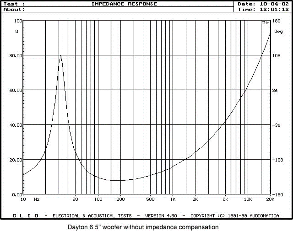
Why Use a Zobel Network and What Does it Do?
A conjugate network, also known as a Zobel network, or an impedance compensation network, is used to flatten out the impedance curve of a driver. All conventional dynamic driver types exhibit rising impedance with increasing frequency. Below are two actual impedance measurements of the Dayton 6.5" woofer, with and without impedance compensation. Note the dramatic difference in the impedance profiles.
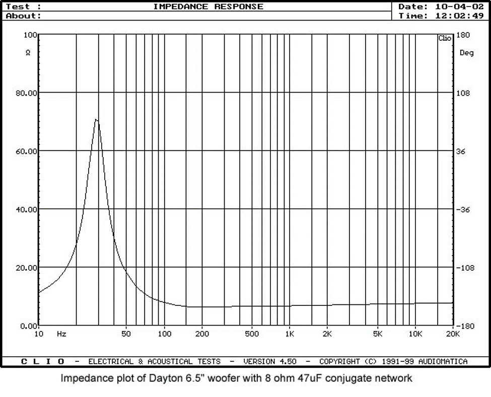
The operation of the crossover network is completely dependent on the impedance of the drivers. Having a flat impedance curve is very helpful in crossover design because it enables the filters to act in a more predictable manner. A conjugate network is highly recommended when implementing a crossover from textbook calculations.
How Close Do My Values Need to Be?
When constructing crossovers, it is generally recommended to keep actual component values within 10% of the calculated values. Small changes in values will cause minor changes in frequency response. However, if you are going to be using multiple values that are in error, try to use one that errs on the high side, and one that errs on the low side. This way, the overall error will be minimized.
What if I Can't Find the Exact Value That I Need?
If you cannot find a value that is within 10% or so of your desired value, there are a couple of things that can be done. Here are some suggestions for dealing with the various components.
Capacitors:
Combine two capacitors by connecting them in parallel. Using them this way you can simply add the two values together to get the total equivalent capacitance.
Resistors:
Connect two resistors in series to provide a total resistance that is equivalent to the values of both added together. The wattage rating on both resistors must be high enough to meet the design requirements.
Inductors:
For the most part, you do not want to use multiple inductors if at all possible. One suggested method for getting a custom value is to buy an oversized inductor, and then unwind some coils until you get to your target value. The drawback to this method is that some type of inductance meter must be used to determine when the target is reached. See the component selection guide for information on working with inductors.
What Are the Differences in Capacitors?
There are a wide variety of capacitors available for use in crossover networks, each with their own characteristics. The 3 main types of capacitors are non-polar electrolytic, metallized polypropylene, and film and foil.
Electrolytic capacitors are the most inexpensive, and are generally used when budget is the primary concern. Electrolytic capacitors are often described as imparting a grainy or harsh sound to the input signal. If an electrolytic capacitor is to be used, usually it is best in woofer or subwoofer situations, where the large capacitor values needed make electrolytics the only economically feasible alternative. When electrolytics must be used, a second smaller capacitor of higher quality is often used in parallel to help improve overall performance. The greater the portion of the total capacitance that is made of the higher quality component, the better.
Metallized Polypropylene capacitors are the most widely used in crossovers because of their availability in a wide range of values and their great balance between cost and performance. Metallized polypropylene capacitors are constructed using a thin layer of metal that is deposited onto a polypropylene film, and then both are wrapped up to fit into a small cylinder. Most polypropylene capacitors feature roughly the same overall sound quality, though there are slight variations from brand to brand. Polypropylene capacitors are usually described as having a smooth and accurate sound, though lacking in the ultimate detail and clarity seen in some Film and Foil capacitors. As a high-quality capacitor, polypropylenes are used in all but the most extreme designs.
Film and foil capacitors are the most expensive type, using two separate layers-- one of actual metal foil, and one of a dielectric film. The greater conductivity of the pure metal film contributes to improved clarity and detail. Film and foil capacitors are considered to be the best sounding, of course at an increased cost. Small value film and foil capacitors are often used as bypass capacitors, meaning they are placed in parallel with lesser quality capacitors. The amount of improvement in sound quality using this method is dependent on the ratio of film and foil to other capacitor types.
What Are the Differences in Inductors?
Inductors range from air core to iron core, with gauges ranging from 20 gauge up to 14 gauge and beyond. When choosing an inductor, one of the primary concerns is to keep the DCR (DC resistance) to a minimum. A high DCR will cause power loss and erroneous operation of the crossover. In some situations, a crossover circuit may be designed around an inductor with a high DCR, but for general textbook crossovers, the lower DCR the better. Because of the increased copper necessary to minimize DCR, you will find that the smaller gauge (thicker wire) inductors are more expensive. It is one of the many judgement calls in speaker building to decide how much to spend on an inductor.
In tweeter crossovers, the inductors one is dealing with are generally smaller in value. Because of the smaller values, the DCR is usually fairly low. As a result you will often see 18 or 20 gauge inductors used in tweeter sections.
In terms of audio quality, air core inductors have superior properties compared to other types. Most often, alternatives to air core inductors are ferrite core or iron core. Ferrite cores should be avoided in most situations, while iron core inductors do have some uses. The metallic cores increase the inductive capacity of a given coil size, enabling a shorter length of wire to be used, thus reducing the DCR. Iron core inductors suffer from several problems including hysteresis loss and eddy currents, and should be used prudently, usually only when large value inductors are needed. In subwoofer applications, iron core inductors are considered acceptable due to the low sensitivity of the human ear to distortions in this area.
One last type of inductor is a specialty type, the foil variety. These are constructed by coiling up a thin layer of metal with a dielectric between layers. Foil inductors offer superior inductive properties that are closer to the mathematically ideal model.
What Are the Differences Between Resistors?
Probably the most important factor when choosing a resistor for use in a crossover is to make sure that it is non-inductive. Many standard high-power resistors have a high inductance, which will cause erroneous crossover performance. A non-inductive type will yield accurate and predictable results. For improved sonic characteristics, audiophile type resistors are available, such as the Mills resistors. Mills resistors are known for having superior overall sound quality compared to most standard resistors.