Constant Voltage (70-Volt) Audio Systems
As common and useful as they are in commercial applications, there is often some amount of "mystery" attached to constant-voltage audio systems, commonly referred to as "70-volt", "25-volt" or "100/140-volt" systems.
The following excerpt from Audio System Design And Installation, by G. H. Philip Giddings is an explanation of these systems.
7.10 High-Impedance Loudspeaker Distribution
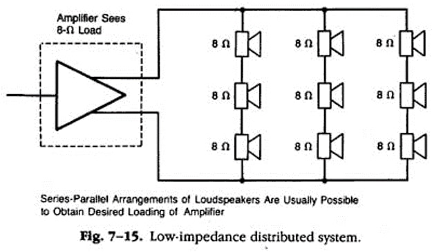
Many sound systems require that many loudspeakers be driven from a single amplifier. While it is possible to take an amplifier designed to drive a single 8ΩW, speaker and by putting speakers in parallel and series drive almost as many 8ΩW speakers as desired, as shown in Fig. 7-15, this system is difficult to install, unreliable, and inflexible. To overcome these and many other shortcomings a system known as constant-voltage or high-impedance loudspeaker distribution has evolved. These systems are also referred to by their nominal voltage with 70-V systems and 25-V systems being the most common.
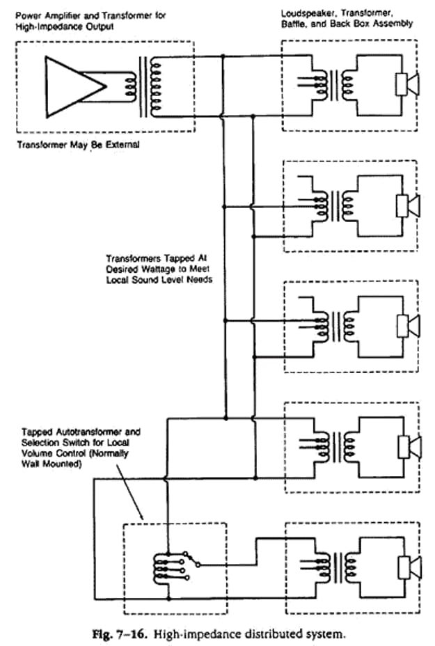
These systems make use of amplifiers which provide a constant nominal output voltage, typically 25, 70.7, or 140 V, for any load resistance up to the amplifier's rated load and use transformers at the loudspeakers to convert the high-voltage, high-impedance signal to a low-voltage, high-current output required by the loudspeaker as illustrated in Fig. 7-16. These systems have the advantages given in the following list:
- All loudspeaker transformers are wired in parallel across the amplifier output, making wiring simple.
- If one loudspeaker or loudspeaker transformer goes faulty and opens, the remaining speakers continue to operate.
- The loudspeaker transformers generally have assorted primary winding taps allowing different power levels to be selected for each speaker. The individual loudspeaker power level can be easily adjusted after the system is installed. Using switch-selected transformers provides volume controls at the individual loudspeakers.
- Loudspeaker transformers with secondary taps for 4-, 8-, and 16ΩW loudspeakers allows for simple design and installation, and selection of desired power level to loudspeaker.
- Adding or removing a loudspeaker from the system does not change the signal level to the other speakers due to the constant voltage output of the amplifier.
- High-impedance loudspeaker distribution systems being higher voltage and lower current than low-impedance (4 to 8 ΩW) loudspeaker systems have the following features:
- Higher operating voltage means less power is consumed by copper resistance
- Longer lines can be run before wire resistance becomes a concern
- Lower operating current means that thinner wire can be used
7.10.1 High-Impedance Loudspeaker System Considerations
The choice of which voltage is best for a given; application varies. The higher the system voltage the less copper is required to transfer the power to the load. This becomes significant in systems of large magnitude or physical distance. In many cases, however, as the voltage of the system rises the electrical code safety requirements also escalate. In many locations 25-V systems are considered low-voltage and do not come under the jurisdiction of the local codes and inspectors. This may allow cost savings in wiring practices and materials. In North America both the 25- and 70.7-V systems are widespread, with the latter being the most common with a wealth of hardware being available for such systems. When installing large systems it is worthwhile to test the impedance of the loudspeaker lines prior to connection to the amplifier. Many possible errors in installation can be found this way. An impedance bridge is normally used for this purpose although the same thing can be accomplished using a test tone, a voltmeter, and an ammeter. Table 7-3 gives the impedances and current flows that are expected from various loads, where Z is the load impedance. This table should be photocopied and kept in the installer's tool kit. As a rule of thumb, the impedance expected on a 70.7- (25-) V line is 5000 (625) divided by the total watts (the sum of all the transformer taps) (Note: R = E * E/P). This should not exceed the rating of the amplifier driving the line. To understand the operating theory of the high-impedance loudspeaker distribution system consider the following basic math:
P = E² ÷ R
where P is the power, E is the voltage, and R is the resistance.
For a 70.7-V system, P = 5000 / R gives the power when the load is known, R = 5000 * P gives the load when the system power is known.
For a 25-V system, P = 625/R gives the power when the load is known, R = 625 * P gives the load when the system power is known.
Now consider the following example. A 250-W 70-V amplifier will deliver 250 W if it is connected to a load that draws 250 W Using the formula P= E * E/R, such a load is given by R= E * E/P = 70.7 * 70.7/250 = 5000/250 = 20 ΩW. A typical 70-V transformer used at, say, a paging loudspeaker would have primary taps at 0.25, 0.5, 1, 2, 4 W to draw 1 W from the 70-V line the 1-W primary tap must have a resistance of R = E * E/P= 5000/1 = 5000 0; similarly, at 4 W the load is 1250 ΩW. If two transformers tapped at 1 W are in place across the line the amplifier load is 2500 ΩW and 2 W total are being delivered. As more and more loudspeaker transformers are installed across the amplifier the load increases according to the sum of the taps of all the transformers. When the total of all the loudspeaker transformer taps reaches 250 W (in our example) the load will be 20 ΩW, and all of the power (250 W) will be drawn from the amplifier. If the sum of the taps of the loudspeaker transformers exceeds 250 W then the amplifier will be operating into less than 20 ΩW and will be exceeding its rating. In this situation the amplifier may exhibit one or more of the following: overheating, shutdown, instability, and drop in output level resulting in an overall level decrease in the system.
Table 7-3 is useful in designing and checking high-impedance distribution systems. The upper part of the table indicates what loads and currents result for certain power loads, which is useful for checking amplifier loads during setup. The lower part of the table indicates the currents and loads which individual loudspeaker transformers should draw, which is useful for verifying their performance.
| Table 7-3. High-Impedance Loudspeaker Distribution Current/Voltage/Power Relationships | ||||||||||
| Power | 25 V | 50 V | 70.7 V | 100 V | 140 V | |||||
| (W) | Z | I | Z | I | Z | I | Z | I | Z | I |
| 1000 | 0.63 | 39.8 | 7.5 | 20.0 | 5 | 14.1 | 10 | 10 | 19.6 | 7.14 |
| 500 | 1.25 | 20.0 | 5.0 | 10.0 | 10 | 7.07 | 20 | 5.0 | 39.2 | 3.57 |
| 250 | 2.5 | 10 | 10 | 5.0 | 20 | 3.54 | 40 | 2.5 | 78.4 | 1.79 |
| 200 | 3.13 | 8.0 | 12.5 | 4.0 | 25 | 2.83 | 50 | 2.0 | 98 | 1.43 |
| 150 | 4.17 | 6.0 | 16.7 | 3.0 | 33.32 | 2.12 | 66.7 | 1.5 | 130.7 | 1.07 |
| 100 | 6.25 | 4.0 | 25 | 2.0 | 50 | 1.41 | 100 | 1.0 | 196 | 0.71 |
| 75 | 8.33 | 3.0 | 33.3 | 1.5 | 66.6 | 1.06 | 133.3 | 0.75 | 261.3 | 0.54 |
| 50 | 12.5 | 2.0 | 50 | 1.0 | 100 | 0.71 | 200 | 0.50 | 392 | 0.36 |
| 25 | 25 | 1.0 | 100 | 0.50 | 200 | 0.35 | 400 | 0.25 | 784 | 0.18 |
| 16 | 39.1 | 0.64 | 156.3 | 0.32 | 312.4 | 0.23 | 625 | 0.16 | 1225 | 0.11 |
| 10 | 67.5 | 0.40 | 250 | 0.50 | 499.9 | 0.14 | 1000 | 0.10 | 1960 | 0.07 |
| 8 | 78.1 | 0.32 | 312.5 | 0.16 | 624.8 | 0.11 | 1.25K | 0.08 | 2.45 | 0.06 |
| 5 | 125 | 0.20 | 500 | 0.10 | 999.7 | 0.071 | 2.00K | 0.05 | 3.92K | 0.036 |
| 4 | 156.3 | 0.16 | 625 | 0.08 | 1.25K | 0.057 | 2.50K | 0.04 | 4.90K | 0.029 |
| 2 | 312..5 | 0.08 | 1.25K | 0.04 | 2.50K | 0.028 | 5.00K | 0.02 | 9.80K | 0.014 |
| 1 | 625 | 0.04 | 2.50K | 0.02 | 5.00K | 0.014 | 10.0K | 0.01 | 19.6K | 0.007 |
| 0.5 | 1.25K | 0.02 | 5.00K | 0.01 | 10.0K | 0.007 | 20.0K | 0.005 | 39.2K | 0.004 |
| 0.25 | 2.50K | 0.01 | 10.0K | 0.005 | 20.0K | 0.004 | 40.0K | 0.003 | 78.4K | 0.002 |
| 0.125 | 5.00K | 0.005 | 20.0K | 0.003 | 40.0K | 0.002 | 80.0K | 0.002 | 156K | 0.001 |
7.10.2 High-Impedance Loudspeaker Power Amplifiers
The characteristic feature of a constant voltage amplifier is that it produces the nominal operating voltage of the particular system at full power, such as 25 or 70 V. Its output is regulated enabling it to maintain this voltage regardless of the load applied so long as this is equal to or less than the power rating of the amplifier output. This is accomplished with a solid-state low-impedance amplifier of the desired power rating driving a output transformer which steps up this output voltage (in most cases) to the nominal system voltage. In most cases, dedicated amplifiers with 25- and/or 70.7-V outputs are used although this does not have to be the case. The nature of most modern solid-state amplifiers is such that outputs are constant voltage as long as the amplifier rating is not exceeded. For example, the wattage required to obtain the various high-impedance distribution system voltages when a transformer is not used are given in Table 7-4.
A low-impedance amplifier with a 250-W output into 8 ΩW produces a maximum average voltage of 44.7 V. This voltage will overdrive a 25-V system and underdrive a 70.7-V system.
7.10.3 High-Impedance Loudspeaker Transformers
The purpose of the loudspeaker transformers in these systems is to match the loudspeaker voice coil impedance (4 or 8 ΩW, usually) to the system impedance and to do this in a way which provides the desired power to the loudspeaker. Considering the following example will illustrate what the transformer does. Consider a loudspeaker which is to be driven from a 70.7-V line with 8 W. Putting 8 W into 8 ΩW requires 8 V (E= ΩÖPR). We have to step down the system voltage by a factor of 70-7/8 or 8.84/1, and we know from transformer theory that this must therefore be the turns ratio of the transformer. Another way to consider this is that the secondary of the transformer sees the 8-ΩW loudspeaker voice coil and the transformer must match this to the 625 ΩW (see Table 7-3 for this number) that the 70.7-V line wants to see for an 8-W load. The turns ratio squared is the impedance ratio; 8 ΩW times 78.1 (8.84 squared) equals 625, which is the desired load to the 70.7-V line. Not included in this simple analysis is the loss in the transformer, which is typically less than 1 dB in the better designs.
| Table 7-4. Amplifier Ratings High-Impedance System without Transformer | |
| Nominal System Voltage (V) | Amplifier Rating |
| 25 | 78 W into 8 ΩW |
| 50312 W into 8 ΩW | |
| 70.7625 W into 8 ΩW | |
| 1001250 W into 8 ΩW | |
| 1402450 W into 8 ΩW | |
It is important that the transformer draw the correct amount of power from the line and that this is constant at all frequencies. The audio system designer should verify whether the power rating of the tap is the power drawn from the line or that delivered to the loudspeaker. If it is the latter then more power than expected will be drawn from the line due to the transformer losses. One of the distinguishing characteristics between well and poorly designed and manufactured transformers is the flatness of the impedance curve or, at least, the absence of dips below the minimum rating of the transformers. Testing has shown that some transformers will, at certain frequencies, draw considerably more power from the line than the power tap rating would suggest. The loudspeaker impedance (in the correct enclosure) will also affect the reflected impedance and load, and testing should be done with a complete transformer/ loudspeaker/enclosure assembly. In large, highly engineered systems with close tolerances (for example, where there is little excess amplifier power) these issues may be a concern.
An autotransformer is often used in high-impedance systems as it allows stepping up and down currents and voltages (impedances) in a simple and low-cost manner. Having only one winding with taps, it is easier to build than most transformers. Unlike a transformer, however, it does not provide isolation between circuits it connects. This is generally not required in high-impedance loudspeaker distribution systems.
7.10.4 High-Impedance Loudspeaker Level Controls
It is often desirable to provide level control in offices and other areas to allow users to adjust their loudspeakers to provide the appropriate level. This is normally done by installation of a multiple-tap transformer or autotransformer and rotary switch combination mounted to a single-gang plate in an electrical device box in the wall. The distributed loudspeaker signal passes through the level control on the way to the local loudspeaker(s) and controls the level of the signal. These devices, normally autotransformers, simply reduce the incoming signal by a certain percentage given by the tap selected. This allows them to work on 25-V, 70-V, or other system voltages. They may or may not replace the transformer at the loudspeaker. They are available in various power levels depending on the number and power ratings of the transformer/loudspeaker combinations that they are driving. 7.10.5 High-Impedance Loudspeaker Priority Override Systems
Many high-impedance distribution systems are used to distribute background music or program sound. In this case local volume controls are installed so that users may adjust the level to their preference. These systems are also often used for paging purposes, which overrides the music or program sound. In such systems it is necessary to override the local volume controls, which may be turned down or off, to ensure all locations receive the page. This is done by means of a control line which is run with the loudspeaker signal and which operates a relay at each level control and overrides the volume setting. These are known as "priority override level controls" and are available from most suppliers of background music and paging system hardware. A power supply (normally of 24 VDC) and switching is required to complete the priority override system.
7.11 Low-Impedance Loudspeaker Interfaces
Low-impedance interconnects are characterized by a solid-state amplifier output driving a loudspeaker of around 8 ΩW normally without the use of transformers. This system provides the most effective means of delivering large amounts of power, at low distortion levels, to one or a few loudspeakers, which are a short distance from the amplifier. This approach is almost always used in high-fidelity applications, such as studio and control rooms, and stage monitor loudspeakers. It is also the simplest and most direct means for large sound reinforcement systems where the total amplifier power ranges from 2 to 100 kW or more. Transformers in either of these applications would either degrade the audio quality or add too much cost, weight, or size.
Reprinted from Audio System Design And Installation, First Edition, First Printing 1990, p.p. 141-148. © Copyright 1990 by G. H. Philip Giddings, USA. All rights reserved.